This is a walkthrough of a hull-leak tester circuit — a rebuild of the old VDO panel unit from the HullSentry origin story. From the outside it could not be simpler: three wires (battery plus, battery minus, hull), a green lamp that means “the tester is alive”, and two push-buttons. Hold TEST+ to check for a leak from battery-plus to the hull, TEST− for a leak from battery-minus to the hull. A row of four red LEDs lights one step per 10 mA of leak current, up to 40 mA.
No electronics background is assumed here beyond knowing part names. Only one idea is genuinely needed: current through a resistor produces a voltage across it (Ohm’s law), so if you force a current through a known resistor, reading the voltage tells you the current.
Why this is not a five-part circuit
A leak is an unwanted resistive path between the battery wiring and the hull — a chafed wire, a screw through a cable, salt-crusted grime. Direct current through that path eats the aluminium where the current exits: roughly three grams per year per milliamp, concentrated on one pit. To detect it, the tester briefly completes the leak’s circuit: connect the hull to the opposite battery pole through a measuring resistor, and any leak current has to flow through your measurement on its way home.
That sounds like five parts. Four things make it more than that:
- The two directions are not symmetric. In TEST+, the measured current comes in from the hull and leaves through the tester’s own battery-minus wire — so it can be measured right next to the circuit’s 0 V reference. Easy. In TEST−, the current leaves through the tester’s battery-plus wire and returns to the battery through the boat’s own wiring — it never touches the tester’s minus wire. The only place to measure it is up at battery-plus potential, which on a 24 V bank being equalized can be 34 V above the reference. Measuring a small voltage while “standing” 34 V up is a high-side measurement and needs a dedicated part.
- The supply range is hostile. The same box must work from a tired 12 V battery (~11 V) up to a 24 V bank on winter equalize (~34 V). The measuring chips die above ~32 V, so the electronics need their own small regulated supply.
- The tester must survive success. If the “leak” turns out to be a bolt against the hull, the tester is suddenly connected across the full battery. It has to limit that current, absorb the heat, and disconnect — without dying.
- The tester must not lie. It must never become a hull connection itself (hence spring-loaded buttons that open the moment you let go), and a dark display must be provable — that is what the always-on green lamp is for.
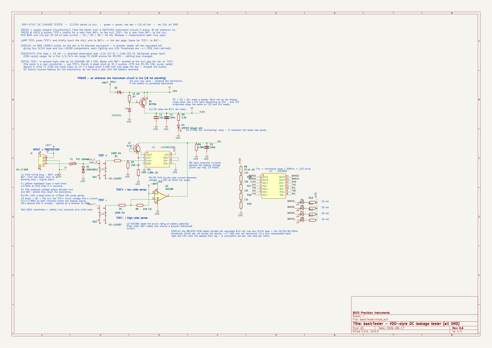
The circuit, part by part
J1 — the three-wire connector. Battery plus, battery minus, and a wire to the hull (a bonding stud or the engine block). Everything else exists between these three wires.
F1 — the resettable fuse. A polyfuse is a resistor that heats up and goes almost open-circuit when too much current flows, then heals when it cools. It sits in the hull wire as the last line of defence: a hard short pushes ~270 mA through the tester, and F1 cuts it off after a few seconds. No fuse to replace afterwards.
D1 — the surge clamp. A TVS diode is a valve that stays closed at normal voltages and snaps open to swallow brief voltage spikes (switching transients, static). It sits between hull and battery-minus so spikes never reach the measuring electronics. Its 36 V stand-off rating is chosen to stay closed even at the 34 V equalize peak.
SW1, SW2 — the buttons. One per test direction. They are momentary on purpose: a leak tester left connected is itself a hull connection, the very fault it hunts. Spring-open on release means the tester can only exist as a leak while your finger insists.
R1, R4 — the ballast resistors. 100 Ω, 4-watt parts. Their job is pessimism: if the leak is a dead short, they are what limits the current (to ~270 mA at worst) and they absorb the heat while F1 makes up its mind. They also keep the range honest: small enough that a 12 V battery can still light all four LEDs.
R2, R5 — the measuring resistors (shunts). 22 Ω each, one per direction. This is where Ohm’s law is put to work: every milliamp of leak current becomes 22 millivolts across the shunt. So each 10 mA step becomes a 0.22 V step — matching, deliberately, the display’s threshold ladder. The shunt value is the calibration; there is nothing to adjust.
U2 — the high-side sensor (INA168). The TEST− shunt rides at battery-plus potential — the asymmetry from the introduction. Reading the 22 mV-per-mA across it is like reading someone’s wristwatch while they stand on a 34-volt ladder and your feet are welded to the floor. The INA168 is a small chip made for exactly this: it tolerates standing up to 60 V above the reference, reads the tiny voltage up there, and reports it down at floor level as a current. (The whole build is surface-mount, sized for ordinary assembly services.)
U3, Q2, R3 — the matching translator for the easy channel. The TEST+ shunt sits at ground, so it could drive the display directly — but then the two channels would interfere where they join. Instead, half of the LM358 op-amp plus one transistor (BC847) convert the shunt voltage into a current (current = shunt voltage ÷ 5.1 kΩ, set by R3 — 5.1 kΩ because it has to match a 5 kΩ conversion factor built into the INA168). Now both channels speak the same language as the INA168’s output. (The op-amp’s second half is simply unused — a dual is cheaper than a single, so it sits tied off, doing nothing.)
R6, C3 — the meeting point. Both channels dump their report-currents into one shared 5.1 kΩ resistor, which turns them back into the voltage the display reads. Why currents? Because an idle current source is effectively invisible — infinitely high resistance — so whichever channel is not being used contributes exactly nothing. Two sources, one reader, no interference, no switching logic. C3 is a small capacitor that smooths the reading.
R8, R15–R18 — the threshold ladder. A chain of resistors hanging from the regulated 8.4 V rail divides it into four taps spaced 0.22 V apart — and 0.22 V across a 22 Ω shunt is 10 mA. Four thresholds made of nothing but a voltage divider. They inherit the rail’s roughly ±10 % tolerance; the vintage dial was no more precise, and a single extra chip (a precision reference) would buy 1 % accuracy back if it ever mattered.
U1, D5–D8, R10–R13 — the comparators and the bar. A comparator is the simplest decision-maker in electronics: two inputs, and the output switches depending on which is higher. The LM339 contains exactly four; each watches the measurement signal against one ladder tap and lights its red LED the moment the signal passes it — four comparators, four taps, four LEDs, nothing clever. Historically one chip — the LM3914 — did all of this internally, but it only ever existed in a through-hole package, so this design simply builds its insides from parts.
D2, R7, D3, Q1, C1, C2 — the private power supply. The op-amp and comparators die above ~32 V, and the battery can be at 34 V. So the electronics run from their own ~8.4 V rail, built the classic way: R7 feeds D3, a 9.1 V zener diode — a pressure-relief valve that holds its voltage steady — and Q1, a transistor, copies that steady voltage while supplying the current the zener alone could not (a “linear regulator” in three parts). D2 is a diode that blocks everything if the battery is ever connected backwards. C1 and C2 are reservoir capacitors that keep the rail smooth. A side benefit: LED brightness is identical on 12 V and 24 V boats.
R9, D4 — the green lamp. Fed from the 8.4 V rail, lit whenever the tester has power. This answers the question every dark indicator raises: is it dark because everything is fine, or because the tester is broken? Green on + red bar dark = genuinely below 10 mA. The unit draws about 8 mA whenever powered, so it belongs on the switched instrument circuit — green comes on with your nav instruments, exactly like the original VDO unit.
Numbers worth knowing
- Thresholds: 22 Ω × 10 mA = 0.22 V per step, matching the ladder taps. Accuracy is rail-tolerance class (~±10 %) — the same league as the vintage dial; the steps stay in exact ratio to each other regardless.
- Smallest detectable leak: the first LED needs 10 mA, which means ~1.2 kΩ of leak resistance on 12 V (~2.6 kΩ on 24 V). This is deliberately a gross fault range, in the spirit of the VDO’s dial. Swapping the two shunts to 220 Ω turns the same circuit into a fine 1/2/3/4 mA instrument — nothing else changes.
- Worst case: a dead short at 34 V pushes ~270 mA; R1/R4 absorb it, F1 disconnects it. At 12 V a dead short (~100 mA) simply pegs the bar — release the button.
- One honest caveat: on boats where battery-minus is deliberately bonded to the hull, TEST− pegs the bar — correctly, since the bond is a connection. Only TEST+ is meaningful there.
Where this stops
A push-button tester knows the truth only while your finger is on it. Leaks that come and go — the ones that do the real damage — need the same measurement repeated automatically, with far finer resolution. That is HullSentry’s job: every 10 minutes, four battery banks, microamp-class sensitivity, and a memory.
basicTester vs HullSentry
| basicTester | HullSentry | |
|---|---|---|
| 12 V / 24 V | ✅ | ✅ |
| Both poles (+ and −) | ✅ | ✅ |
| Colour-coded display | ✅ | ✅ |
| Power-on pilot | ✅ | ✅ |
| Reverse-polarity protection | ✅ | ✅ |
| Surge protection | ✅ | ✅ |
| Panel mount | ✅ | ✅ |
| Automatic measurement every 10 minutes | ✅ | |
| 4 battery banks (8 wires) | ✅ | |
| Reading in ohms | ✅ | |
| Microamp sensitivity | ✅ | |
| Simultaneous leaks separated | ✅ | |
| Per-bank voltage | ✅ | |
| Real-time clock timestamps | ✅ | |
| microSD logging | ✅ | |
| History and trends | ✅ | |
| Warning / alarm thresholds | ✅ | |
| Buzzer + mute | ✅ | |
| Dry-contact relay output | ✅ | |
| Wi-Fi | ✅ | |
| Email alerts | ✅ | |
| Web dashboard | ✅ | |
| .csv export | ✅ | |
| Audio troubleshooting mode | ✅ | |
| 20 × 4 LCD | ✅ | |
| Auto-dimming backlight | ✅ | |
| Galvanically isolated input | ✅ | |
| Over / under-voltage cutout | ✅ | |
| One button per function | ✅ | |
| Firmware updates | ✅ |